WINGED WARRIORS/NATIONAL B-BODY OWNER ASSOCIATION
DISC BRAKE CALIPER REBUILD TECH
TEXT AND PHOTOS BY SUE GEORGE
If you notice excessive pulling to one side when you apply the brakes or if the front brakes seem to overheat and you suspect they are not releasing, chances are one of the calipers has a frozen piston. If you're going to the trouble of removing the caliper to free up the piston, now is the time to rebuild the whole system for many years of trouble-free braking.
Brake fluid leaking around the caliper is a good indication the seals are shot. This also warrants a caliper rebuild. Although calipers for most of the late 60s and 70s Mopars are still available (some of the double piston calipers are VERY expensive), it is easy and inexpensive to rebuild your original calipers, as long as the cylinder bore is still in pretty good shape.
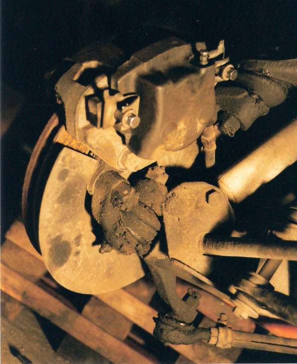
Before you begin, pull of the tire/wheel and take a good look at the entire caliper assembly to familiarize yourself with your particular style of caliper assembly. I have provided photos here of a 1970 Kelsey Hayes floating caliper set-up we rebuilt on a Superbird. This will generally resemble what is on most of our Mopar musclecars.
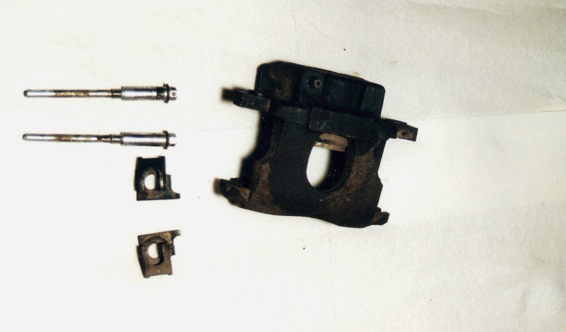
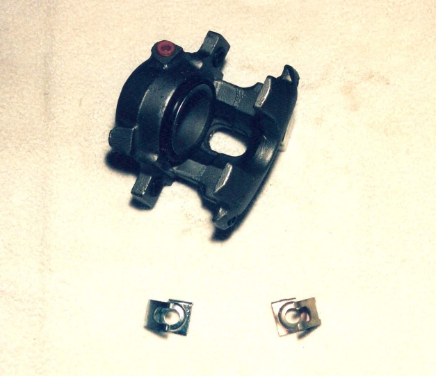
An air compressor and micrometer will be needed. The easiest way to begin is to first break the flexible hose fitting loose while you can use the rotor for leverage. Next remove the long pins (bolts) and positioners, which look like little square spring clips. (Photo #3 below) that attach the caliper to the adapter on the rotor. Carefully slide the caliper out and away from the rotor, while you hold onto the outboard brake pad, as it will come out with the caliper. Remove the inboard brake pad. Now spin the caliper off of the flexible brake hose and plug the end of the hose with a bolt to prevent loss of your brake fluid Otherwise, you will have to break the flexible hose fitting away from the steel line connection at the car's frame mounting bracket, remove the clip and then pull the flexible hose through the bracket hole. You will then remove the flexible hose from the caliper after it is taken off the rotor. Not only is this a hard place to work in, but it is not unusual for this connection at the frame to seize and the brake line can easily twist off.
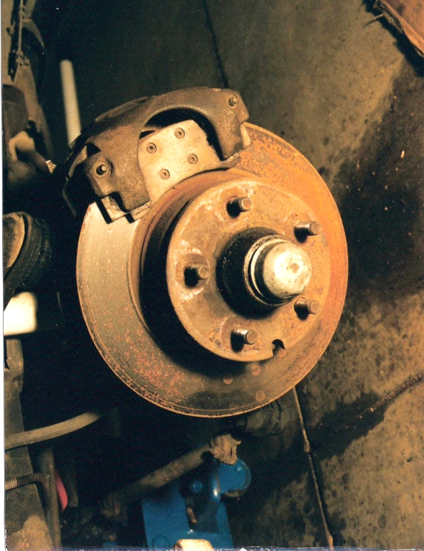
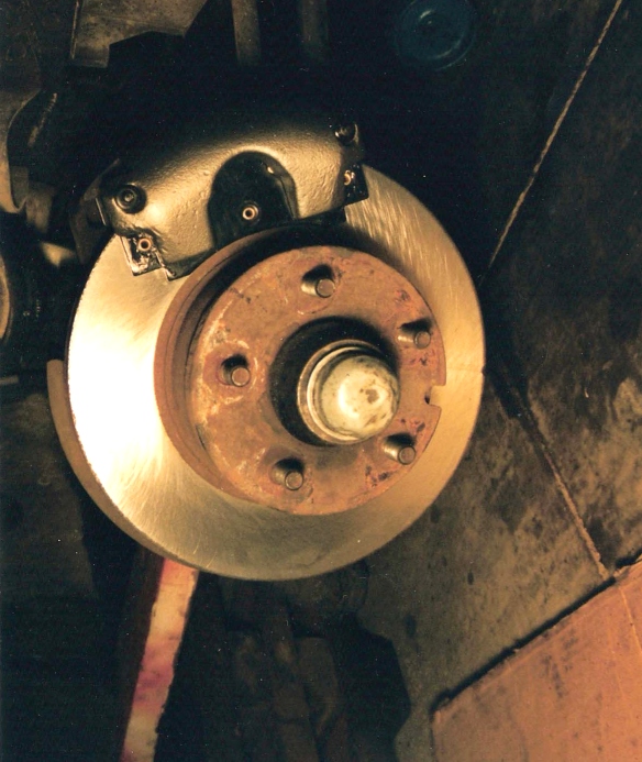
Left to right: Photo #1 The back side of the caliper assembly still mounted on the rotor. Note how the positioners are situated on the caliper pins. Photo #2 The outer surface of the rotor with the caliper mounted. Note the brake pad's position inside the caliper. Photo #3 Caliper housing, positioners and pins.
Now is the time to visually inspect the brake pads for wear. The service manual says three thickness measurements should be taken, with a micrometer, across the center of the brake pad lining, one at each end and one in the middle. Replace the pad if any measurement is .180 inch or less.
The inboard brake pad will show slightly more wear than the outboard pad, which is normal. If your car still has the factory riveted brake pads, replace them now. The brake pads available now are made out of superior materials and have wear indicators so you can tell when they're about shot before they grind away your rotors.
This is also a good time to inspect the rotors. Very light surface rust can be removed with emery cloth. If there are ridges, deep rust or pits, the rotor needs to be sent to the machine shop for refacing.


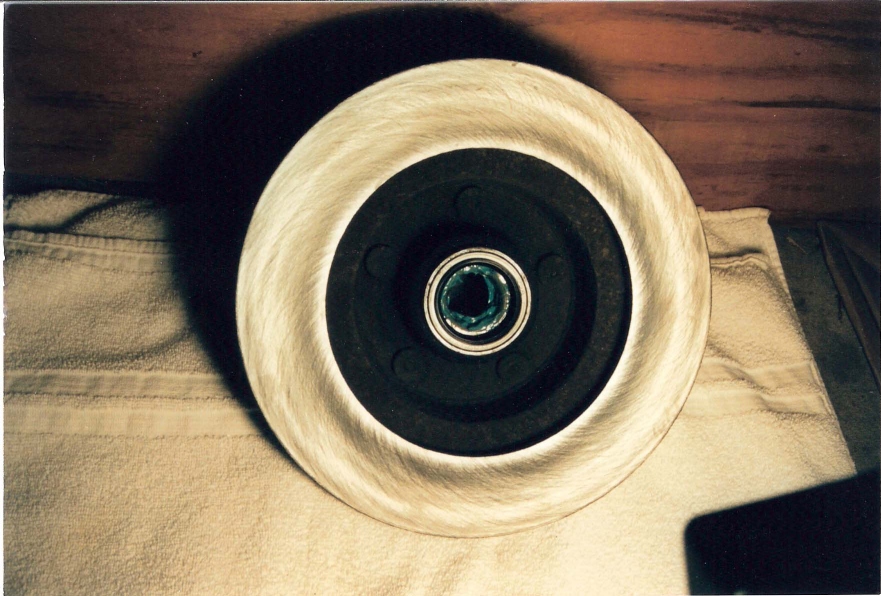
From left to right: Photo #4 New Raybestos brake pads--modern bonded material with wear indicators that will cause a squeaking noise to alert you that the pads are about gone. No rivets in these pads to grind the rotor face. Retail price approximately $20 at NAPA. Photo #5 Our rotor was heavily rusted with some pitting, and ridges made from worn original brake pads. Photo #6 The same rotor after it was refaced at the machine shop. This rotor is at its minimum thickness of .0980" now.
Each year and style of rotor has a different minimum thickness and discard specification. Any good machine shop will have the book with these listings and be able to determine if your rotor can be refaced or needs to be replaced. The rotor shown in Photo #5 had very heavy rust and some slight ridges from the worn factory riveted brake pads. It was just within it's .980" minimum thickness after refacing, and will have to be replaced next time. The machine shop that refaced our rotors gives the surface a final scuff with an air sander so the brake pads seat quicker.
The reason for minimum thickness specifications for rotors is that it takes that much metal to dissipate the heat generated during braking. Anything less (thinner) than the "discard specifications" recommended by the automobile manufacturer can result in cracked and warped rotors or rotors can even break in half from overheating. The machining and discard specifications for some cars are listed below:
1970-72 RoadRunner, GTX, Belvedere, Satellite; 1970-72 Cuda, 1970 Charger and Coronet: Brand New Rotor nominal thickness is 1"; rotor can be safely machined to .955"; discard rotor at .940"
1969 Charger, Coronet, Dart, Daytona: Brand New Rotor nominal thickness is .886" to .878"; rotor can be safely machined to .816"; discard after that
Now to begin disassembly of the caliper, lay the caliper on a solid surface and slide a board down into the caliper assembly as shown in Photo #7 below. The board will protect the piston from damage by keeping it from slamming against the caliper housing. Place an air compressor hose fitting on the brake hose fitting and blow the piston out of its bore. Don't overdo it here--only a quick burst of air pressure is needed and NOT have your fingers anywhere near the bore!
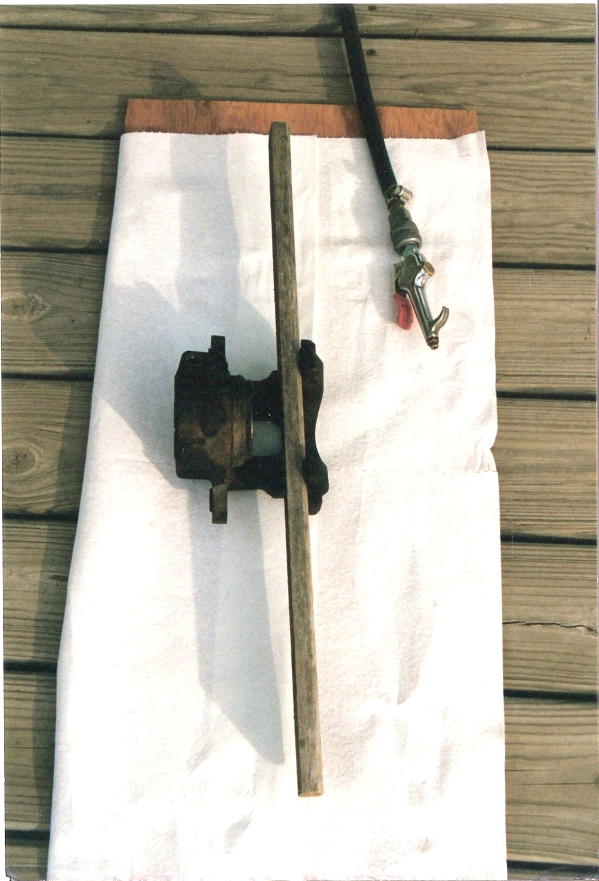

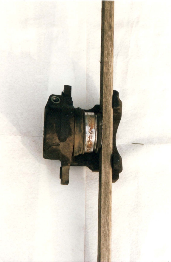
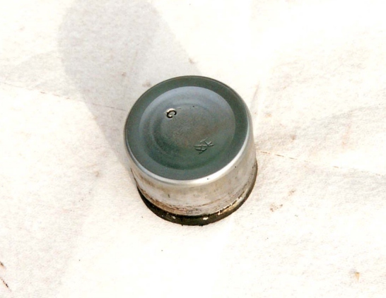
From left to right: Photo #7 Getting ready to blow the piston out of its bore. The board is in place to keep the piston from getting damaged. Do not have your hands down in the caliper when you do this! Photo #8 Place the air hose end on the brake hose fitting on the caliper housing and apply a short burst of air pressure. Photo #9 The piston is out of its bore here. Notice the deep rust and pitting on our piston's finish. Photo #10 Pull the piston the rest of the way out and inspect it for rust, pitting, scratches and worn finish.
The outer dust seal in our caliper was so old and deformed, it partially fell out with the piston. Normally, you would use something plastic or wood and pointed on the end to carefully work the dust seal out of its groove. There is also an inner seal in a groove inside the cylinder bore. Remove it in the same way. Under NO circumstances use anything metal in the cylinder bore or the seal grooves, as this surface cannot be scratched or damaged!
There are rubber bushings in each casting ear of the caliper where the mounting pins slide through the holes. Carefully remove these but DO NOT throw them away unless new ones are included in your rebuild kit. Our Wagner kit did not have new bushing included.

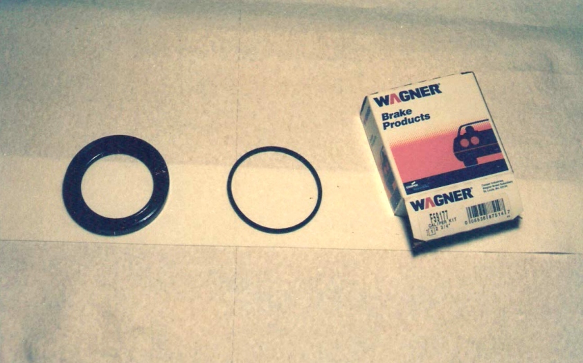
Left to right: Photo #11 Shows the piston bore and the two seal grooves after we removed the seals. Our caliper's bore was deeply scored from the crusty piston, so this caliper was just replaced with a new one. Photo #12 The Wagner kit comes with a new dust seal and inner bore seal. Some kits may also include new mounting pin bushings but don't throw your old ones away until you make sure you have new ones in the kit.
Remove the bleeder screw. These can be purchased separately if they need to be replaced. Clean the caliper housing and piston with solvent and blow dry with the air compressor. If the cylinder bore is lightly scratched or corroded, you can clean it up with a very light emery cloth. If the cylinder bore is deeply scratched or pitted, it can be honed NO MORE than .002" at a machine shop. If the bore can't be cleaned up within this specification, replace the caliper. After honing, make sure you thoroughly clean out the seal grooves before installing the new seals. Also take a look at the condition of the piston. If it's pitted or the plating is worn off, replace it.
Apply silicone grease to the new inner seal (NEVER use brake fluid on the seals!) and install it into the groove in the cylinder bore. Make sure the seal does not twist or roll.
Coat the new dust seal generously with silicone, and leave a lot of it inside the seal. Install the new dust seal into the outer groove of the caliper bore using only your fingers to avoid damage to the seal and the bore. When you first start to put this seal in, it seems like it's way too big, but keep working with it and you'll be surprised to find it fits right into the grooves.
Next, plug the bleeder screw and brake hose holes. Coat the piston with silicone. While you pull apart the new dust seal, push the piston into the cylinder bore. The piston must be exactly straight before it will go in and to avoid damage to the bore. Some cuss words may be required here.
Replace the mounting pin bushing in the caliper casting ears, either with new ones that are supplied in your kit or with the original ones that you saved. Replace the bleeder screw.
Install the assembled mounting pins through the entire caliper-pad-adapter assembly. You'll have to push in on them to start them in the threads. They're fine-threaded, so be very careful not to cross-thread them. Once the mounting pins are installed, the tabs of the positioners will be over the machined surface of the caliper. Torque the mounting pins to 30 ft. lbs.
Open the bleeder screw and gravity-fill the caliper with brake fluid. Close the screw after the air is out of the system. Now you'll have to add fluid to the master cylinder and bleed the brakes.
When you replace the tire/wheel assembly, do not torque the lugnuts over 65 ft. lbs. Anything more will warp the rotors. It doesn't hurt to mention this to the repair shop anytime they will be removing your car's tires and wheels for any reason! Rotors are not cheap to replace!

From left to right: Photo
#13 If you have to replace a caliper, the new caliper assembly comes with new
mounting pin positioners. The cost of our new single piston caliper was a mere
$22.00, although some calipers are very expensive to replace. Photo #14 The
refaced rotor with a new caliper assembly and new brake pads installed. Photo
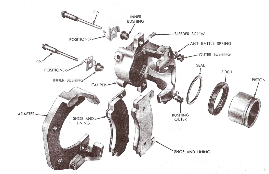
#15 The new assembly installed and shown from the backside. Photo #16 is the
exploded view of the 1970 style Kelsey Hayes brake caliper assembly.
| MAIN PAGE | TABLE OF CONTENTS |