
WINGED WARRIORS/NATIONAL B-BODY OWNERS ASSOCIATION
DAYTONA DETAILS PART 2
text and photos by David Patik
Photos below left to right:
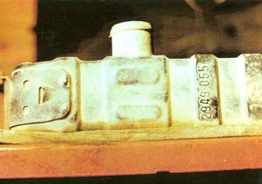
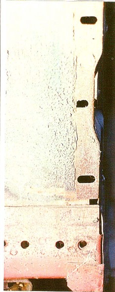
#1 This shows the upper radiator-to-yoke seal #3412698. Note the depth of the seal installation. This seal is 26" long and made of high-density foam. There is no paint on this seal. Also notice that the radiator part number shown here reflects a car without the maximum cooling package.
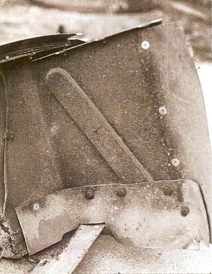
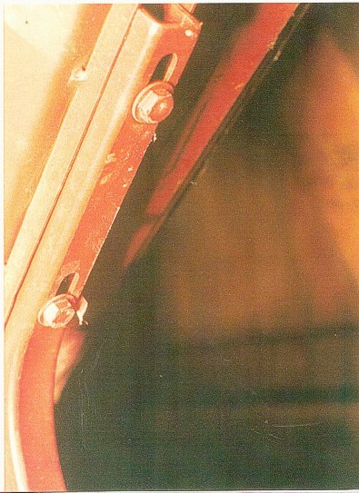
#2 Shown in this photo are the seals on the nosecone bulkhead. There are three large-headed pop rivets on the vertical seal #3412679. The horizontal seal #3412695 uses one pop rivet. Nuts are used on the remainder of both seals (one bolt passes through both seal). These seals are placed over the first set of nuts, they attach the bumper bolts.
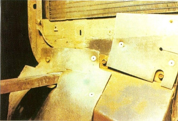
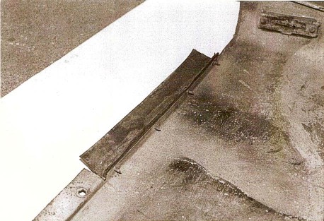
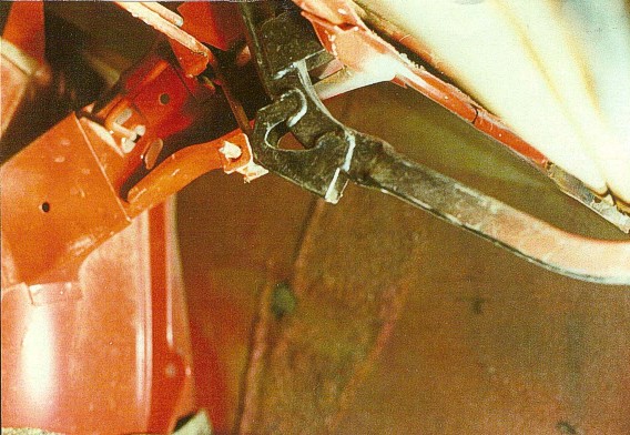
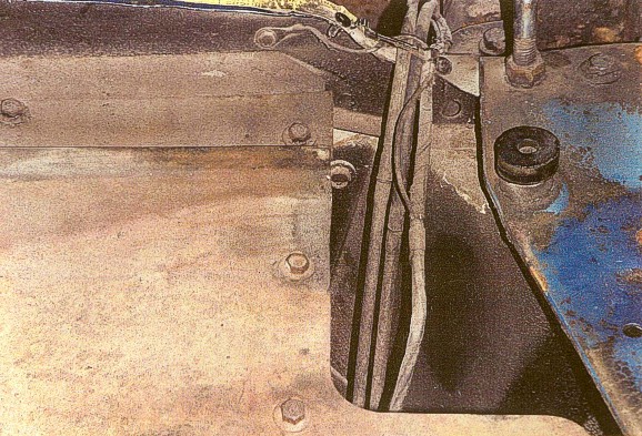
#3 This photo shows the tie-bar supports. Notice it mounts under the supports and the offset is up and forward. The bar mounts to each support with two 1/4" x 20 bolts and washers.
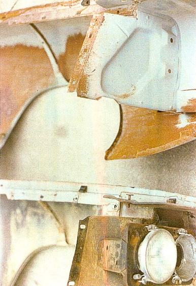
#4. This is the battery cooling hole seal #3412692 (upper left of photo). This is attached with large-headed pop rivets and a 1/4" x 20 bolt, before the left fender is installed. You can also see the large cutout which allows clearance to the fender mounting bolt. The fender-to-valance seal #3412688 (shown in lower right of photo) has the bumper bracket passing through the hole in the seal.
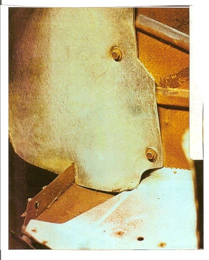
#5. The last photo shows another view of the fender-to-valance seal #3412688. The slot in the outer edge of the seal fits over the fender-valance joint as shown here. These seals are installed before any color coat or black paint or primer.
The six photos below left to right are as follows:
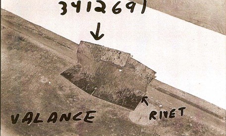
# 1 This is the valance-to-radiator yoke seal #3412691. The seal is attached to the valance with large-headed pop rivets. The split in the longer side faces forward and fits over the bracket attached to the lower yoke. The rear of the seal attaches to the yoke by pushing the seal holes over the the yoke clips.
#2 This is the nose-to-hood seal #2962624. This is the same as a section of a 1970 Charger bumper-to-hood seal. It attaches with long Phillips head screws, which are the same as the washer bottle screws. Clips are 1/4" X 20. This seal €is attached over the nosecone grey primer before color coating.
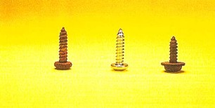
#3. The first two fasteners in this photo are Phillips head screws, used to attach the rubber seals to the fender and valance. The black phosphate finish is correct. The last fastener shown is the Phillips head screw, used to attach the nose-to-hood seal to the top rear of the nosecone.
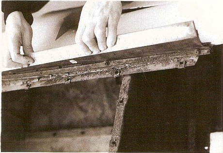
#4. Shown in this photo is the inner right side of the valance. Note the seal #3412681 is screwed to the forward inner surface. This seal is the cut-up section of the 1970 Charger hood-to-bumper. It uses a C-shaped bracket and long Phillips head screws which are the same screws that the washer bottles uses.
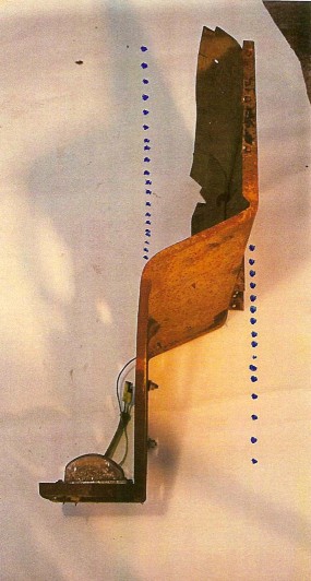
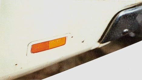
#5. This is another view of the inner right side of the valance. Note the side marker reflector is installed on the grey primer of the valance panel. The lens is masked off before paint, but the reflector seal is not. After the Daytona conversion was done, flat black paint was sprayed on the inside of the valance behind the fender-to-valance seal.
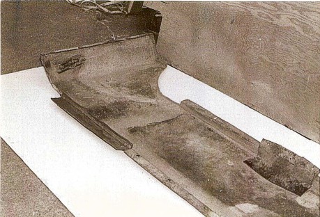
#6 The last photo shows the left front view of the valance. This is the correct installation of the seal and metal holding strip #3412680. You can see the remains of flat black overspray on this valance.
The photos below from left to right:
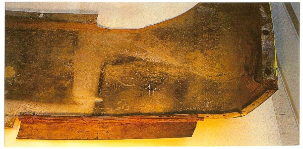
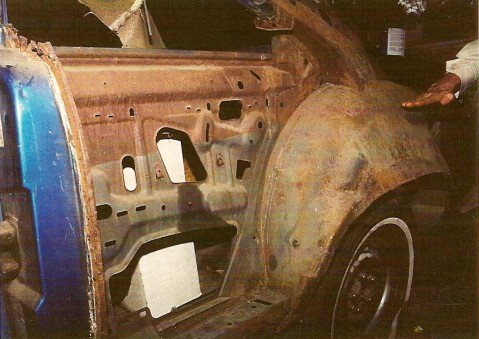
#1. This is the inner left quarter panel of a 1968 Hemi RoadRunner. I included it here because it shows the procedure for primering at the assembly plant. Notice the level of dip primer on the inner body (the hand is at the level of primer which shows as the lighter area on the lower part of the panel). Cars were dunked to the level of the headlights. This is true of Daytonas before the conversion.
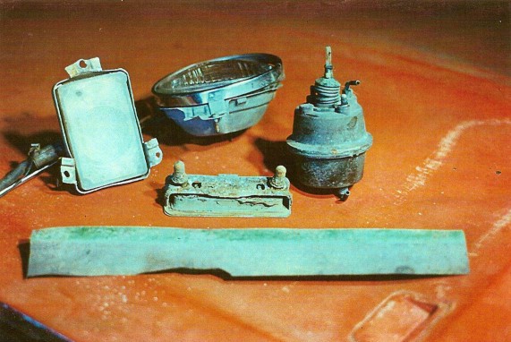
#2. The components shown here, and many more, will show body color overspray, usually minimal.
#3. From left to right these fasteners are: (a) Park lamps grommet; (b) Screw for grommet, large headed Philips head, length is 1/2"; (c) Ground wire terminal from park lamp, attaches to the bulkhead. This should not be painted or broken off its wire.
#4. Shown here is the left forward edge of the Daytona front fender. Notice the lack of body color on the primer where the nose-to-fender seal was mounted (the white part of the photo).
#5. The last photo shows the left side of the Daytona hood. Three Phillips head chrome screws are used plus one annodized (not chromed) screw is used to attach the lanyard. The correct lanyard length is 18". The lanyard is plastic coated. The correct hood clip is flat as shown.
The four photos below are as follows:
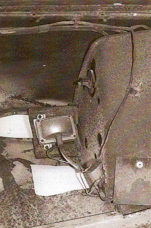
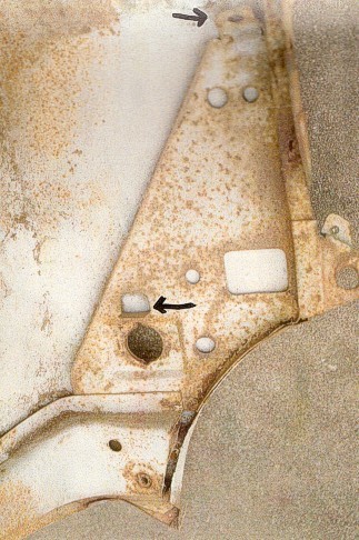
#1 This is the inner view of the left bulkhead. Large headed pop rivets are used to attach the horizontal rubber seal. 5/16' X 18 nuts with small captive washers attach the seal. Under the seal, another nut and washer attaches the bulkhead-to-bumper bracket. Notice the black grommet with the Phillips screw in the center of the bulkhead. It holds the park lamp wire. Note the partially hidden 5/16" headed screw under the rubber. This is the ground wire.
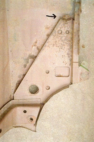
#2 This is another view of the inner left bulkhead. Notice the placement of the vertical seal under the horizontal seal. Large headed pop rivets attach the vertical seal. The yellow overspray on these parts is excessive because of repairs to the nose.
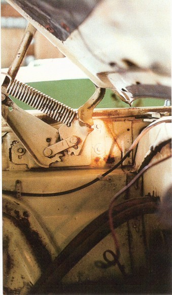
#3. This is the right Daytona deck lid hinge. There is black primer on the hinge at this point. Notice the sound deadener spray pattern. There is color coating on the sound deadener.
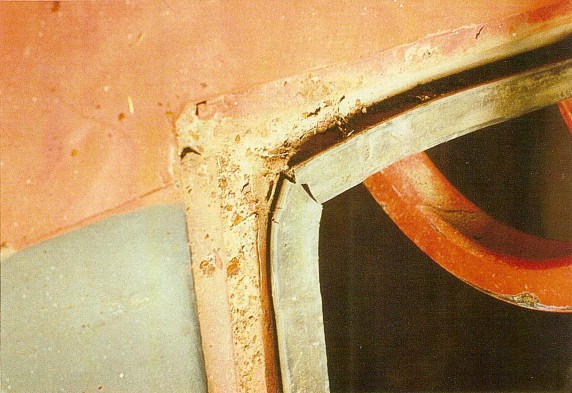
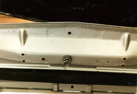
#4. This last photo is a view of the forward left side of the deck lid seal. The original seal was installed on a regular deck lid opening. It was not removed on the forward-to-rear section. It was cut at the new corner, then new sealer was used for the lateral section. Lack of corner sealant results in leaks!
The photos below are as follows left to right:
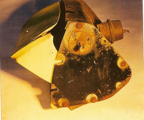
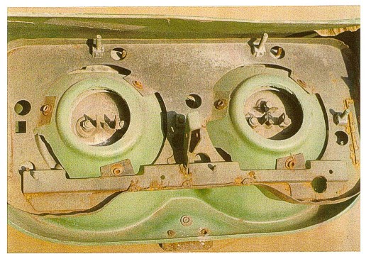
#1. This is the inside view of a Daytona right side headlight assembly. You need to preassemble the fiberglass door, actuator and canister end plate. Note that the endplate is preassembled with (4) 1/4" x 20 bolts. Install the bolts only in the locations shown here. Note that the top bolt and lower left bolt are generic, meaning the head is smooth and the washer is not captive. This is a good example of restoring your car the way it was originally, not the way it ideally was. Often generic hardware is used anywhere inside the Daytona nosecone. There is some yellow overspray showing on the canister end plate (lighter areas around the bolts and shaft). This is incorrect. Also note the broken off stud and missing nut on the shaft adjustment cap.
#2. The second photo is the outside view of a Daytona left headlight assembly. Note the depth of the adjustment slot on the welded-on end cap of the canister. All slots on original Daytona headlight canisters are noticeably deeper than are Superbird slots, even though the canisters and caps are from the same stampings. Also note the correct end cap nuts here.
#3, This is the Daytona headlight, using small rivets on the sides of the fiberglass. Use backside washers on the pop rivets if possible.
#4. Shown second from left in this photo is the special skinny-headed (9/16" head) bolt that attaches the headlight buckets to the nosecone shell.
#5 Shown here is the pin and clip that go on the vacuum actuator-to-headlight bracket.


Photos shown below are from left to right:
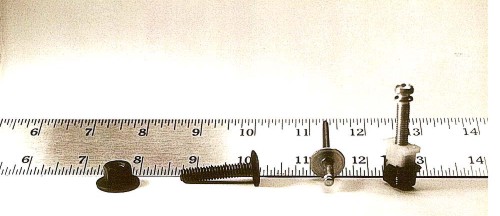
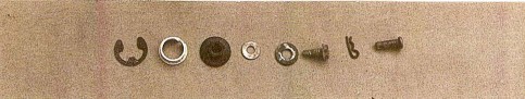
#1. This is the headlight pivot shaft hardware. All of this can come from a C-body car with electric headlamp doors.
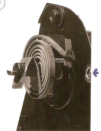
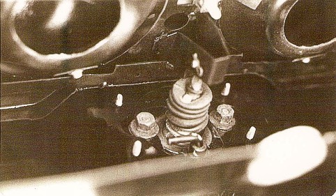
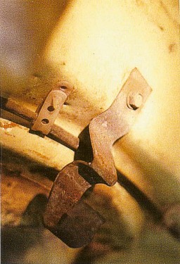
#2. Shown here is the right side detail of the headlamp safety open spring. Note the bolt hole on the extreme right side of the plate. A 5/16" x 18 bolt attaches the spring bracket through this hole. Do not install the tension bracket until all other nose pre-assembly work is done. Note the direction and orientation of the spring. Apparently, these springs are unique to the winged cars. They are similar to window springs but lighter and have a longer arm. Note the incorrect nut attaching shaft adjustment end cap.
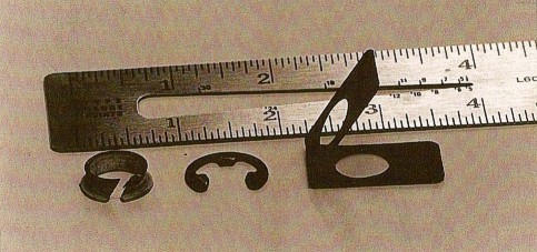
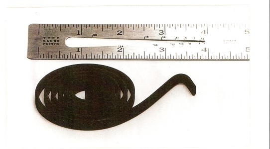
#3. This is an original headlamp safety open spring. The same spring was used on both Daytonas and Superbirds. The width of the metal measures 1/4".
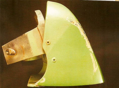
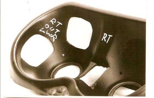
#4. This photo shows the left side headlamp mounting bracket. This front view shows the correct location for the adjuster bolts. This piece is painted flat black before the adjuster bolts are inserted.
#5. These last two photos show the headlamp adjusters correctly mounted for the left side. Large-headed pop rivets are always used on Superbirds, but only on some Daytonas. Notice the original adjuster cut-out holes in the headlamp door.
The six photos below are from left to right:
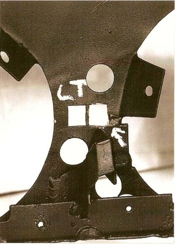
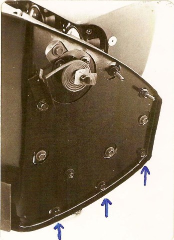
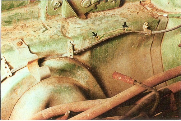
#1. This is the left side headlight mounting bracket. This is the rear view. The arrow shows the hole that the adjuster bolt must be inserted into from the front side. The actuator pin attachment bracket often must be filed away for proper adjuster bolt clearance.
#2. This photo shows the lower center of the Daytona headlight door. Notice that the original doors used a separate metal plate for the stop plate. 'Reproduction pieces are molded-in. Notice the use of small-headed rivets. Underneath the stop plate, the fiberglass door would be gray primer.
#3. This is the right side Daytona headlamp door and complete bracket assembly. Note that pop rivets with backside washers were used on this car (but not on the two lower rivets through the stop plate.) Washers prevent the fiberglass from cracking and should be used especially behind the lower stop plate! This headlight door has considerable green paint on its rear areas due to the car beijg repainted after an accident. Normally very little color would be found here.
#4 -- #6. These are views of the right side headlight buckets.
The photos shown below are as follows:
#1. This is the vacuum chamber #2926951 used on 1969 Charger and Daytona. 1968 Charger uses a different number. The arm length may be different, which is vital to the arc of headlight door opening and closing. To allow the door to close properly, use a washer on each chamber stud, installing the washer to space the chamber away from the adapter plate.
#2. This is the right side headlight bucket pre-assembled. Note that the adapter plate is spaced away from the canister with three washers on each screw. The canister and end plate are painted flat black before assembly, as are all metal stampings. The vacuum chamber is NOT painted. It should be bare, dark silver (pot metal).
#3. Four self threading 5/16" head screws attach the adapter plate to the canister. Original screws have "NL" on the head. Between the adapter plate and the canister are three washers on EACH of the four screws. This is very important!
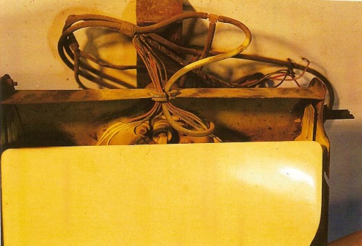
#4, The left side headlight bucket assembly is shown here. The vacuum hose must be installed on the chamber fitting inside of the canister before installing the assembly in the nosecone shell. The yellow striped hose attaches to the connection outside of the canister on both the right and left assemblies. Note the location of the vacuum hose tee fittings.
#5. In this last photo, note installation of the large split rubber grommet around the wires and hoses where they pass through the canister. Wiring and hoses are correctly wrapped here, except on the area where the wires were chopped.

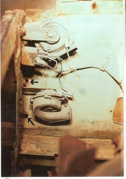
The photos below are as follows:
#1. This is the inner view of a Superbird left bulkhead. Note that the bulkhead has cutouts for some bolt heads or nuts, while others fasten the bulkhead. Arrows show bolt heads of 5/1 6" x 18 bolts that attach the bulkhead to the nose lower seam. Note the long 1/4" x 20 bolts on the upper right of the assembly. They are the skinny-headed bolts that attach the nose shell-to-canister. Also note which bolts show bolt heads or nuts viewed from this side of the bulkhead. The nut/washer shown on the lower left would likely be reversed on Daytonas, so the bolt head was shown. THIS IS A DISPLAY PHOTO ONLY! DO NOT PREASSEMBLE THESE PARTS BEFORE ATTACHING TO THE NOSE SHELL!
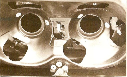
#2. This is the inside view of the headlight canister. To attach the vacuum chamber arm to the headlight bracket, reach into the opening. Insert the pin through the bracket and arm and secure with the spring clip. See the hardware photo #3.
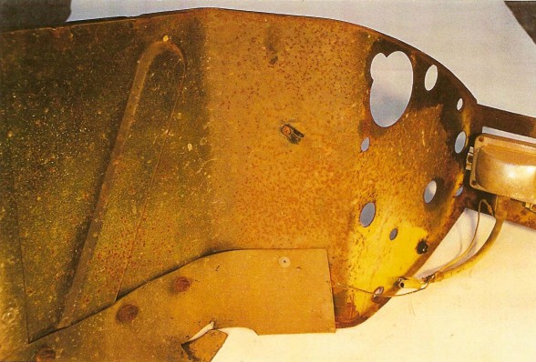
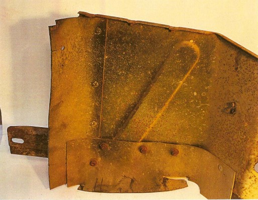
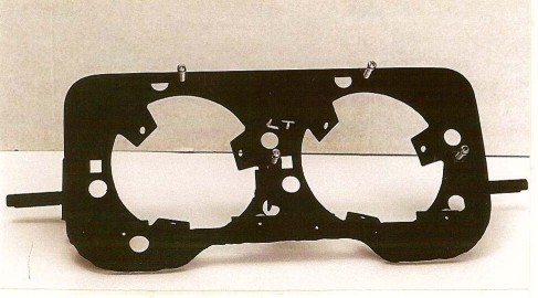
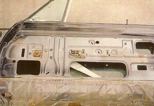
#4. This is the Daytona's left bulkhead. Note that an extension of the planes of the bulkhead are parallel lines. Templates are available to help rebuild wrecked bulkheads. Superbird bulkheads are identical, except for locations of the hood latch tray holes, the wire grommet mounting holes, and of course, the park lamp brackets.
#5. Here is an inside view of a Daytona right side bulkhead. This is another example of individual car variation. The park lamp ground screw on this car shows the terminal above the rubber seal, rather than under it. Some bulkheads have several unused holes in them.

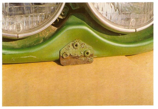
This next three photos below show the inside view of the right hand side of an original Daytona nosecone. The park lamp has three different thicknesses of spacers. There is an explanation of this in the next group of photos.

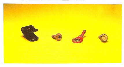
The photos shown below are from left to right:
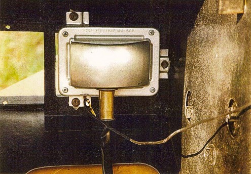
#1. This is the right side Daytona park light assembly. Note that the lettering on the housing reads upside-down. The lens lettering says "R" or "L". These lamps are used from a 1969 Valiant. Only the lens was masked off when the nosecone was painted. This resulted in much color overspray through the grille opening.
#2. Shown in this photo are the Daytona park lamp spacers and screws. From left to right: The top spacer is thinnest, used with a short screw. The middle spacer is the middle thickness and is used with a long screw. The bottom spacer is the thickest and uses a long screw. Spacers were made of solid aluminum. Screws use 1/4" head with a slot. Note the broken heads on the screws in this photo.

The next group of photos are described from left to right:
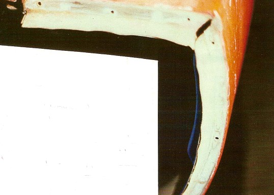
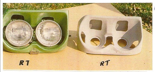
#1. In the upper half of the photo is the left inner 1969 fender, as compared to the left inner 1970 fender in the lower half of the photo. The Daytona uses the 1970 style. Note that the 1969 flange mounts to the side of the inner fender. The 1970 flange mounts to the front of the yoke.
#2. This is a close-up view of the mounting flange on the left inner 1969 fender.
#3. Shown here is the inner right forward edge of the Daytona fender. Note that there is a lack of undercoating and primer where the 1969 fender was mounted prior to the conversion.
#4. This is another view of the inner right Daytona fender. Notice the flat black paint on the front panel and gray primer on the fender-to-inner fender flange. This shows the correct hood pin and hole direction.
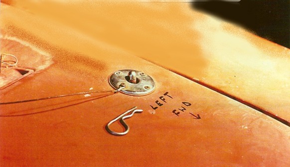
#5. This photo shows the Daytona radiator upper yoke detail. Note the harness ground wire for the headlights. Also note the correct location of the wire and hose grommet, which pokes right through the anti-freeze decal! It's usually located further to the right side of the car. The straight hose connectors are correct. The lack of colored paint on the bracket that attaches the hood latch tray to the upper yoke is correct.


Shown in the photos below from left to right:
#1. This is the Daytona deck lid hinge. Note that there is color coating on the bolts and hinge at this point. The bolts use free-spinning washers.
#2. Shown here is the Daytona jack hold down bracket. This bracket is painted flat black on all sides. The hidden nut and washer are on top of the trunk mat. The nut and washer shown here is correct, however a wing nut was used on some cars. All three washers on this bolt are 1".
#3. Shown in this photo is a Daytona left front inner fender. This was a red Daytona. The light areas are gray primer. Notice that the nose-to-fender seal and the fender-to-valance seal were installed before the blackout paint was applied and NO car color is seen in this area. It is possible that other cars may show color in this area.
#4. These are the Daytona's front jack components. The handle is from some Dodge pickups. The jack was originally made for Chrysler by Custer Manufacturing. Any other uses are unknown. It is likely the cradle locator is a special weld-on. The bracket is a special Daytona part.
#5. This shows the jack bracket bolt head (underneath the car). Notice the free-spinning washer has a 7/16" hole. The bolt is 3/8" x 2" and the threads go all the way to the 9/16" head. Some cars used a 1.75" bolt.


The next group of photos is as follows from left to right:
#1. Shown here is the Daytona wing brace inside the trunk. Note that it was painted gloss black before it was assembled. The hardware was installed in no particular order. Yellow markings are often seen, in no predictable manner, on one or both braces. These marking usually resemble an "X" (see arrows). The bolts have free-spinning attached washers. Nuts are separate from their washers.
#2. This is another view of the wing brace. Note that the bracket is installed to the floor on top of the trunk mat. The correct trunk mat pattern and cut-out is much different than the reproductions that are currently available, but it was the original used from the 1969 Charger.
#3. This photo shows the Daytona wing support bracket bolts from underneath the car. Note that the outboard bolt has a 3/4" washer on it for clearance. The inboard bolt uses a 1" washer. These are free-spinning washers. For reasons unknown, sometimes the bolts were installed upside-down from these.
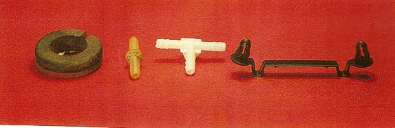
#4. Moving back to the front end of the car, shown here is some of the hardware used in the headlight system, including the rubber grommet used on the back of the headlight bucket, straight vacuum hose connector and T-fitting, the plastic tie used to hold the vacuum hoses in place on top of the radiator support.

Shown in the next group of photos from left to right:
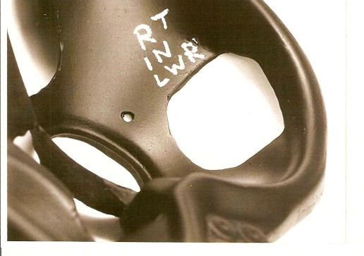
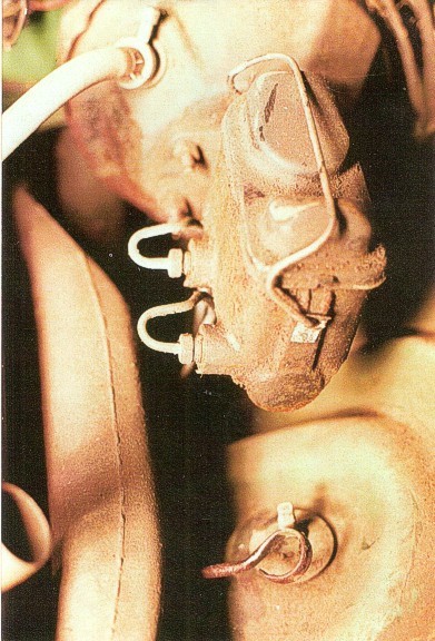
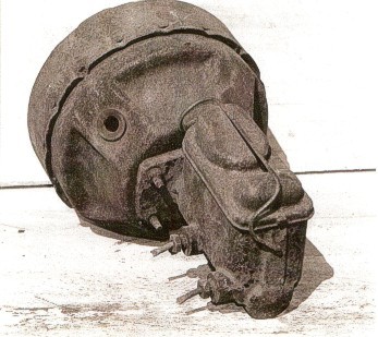
#1 and #2. This is the correct disc brake master cylinder for a 440 Daytona. The vacuum booster and master cylinder are both painted gloss black. The aluminum identification tag is not painted. The master cylinder cover is painted gloss black. The hold-down clip is painted here also. Note this is the correct side (towards the engine) for the brake fluid lines to exit the master cylinder.
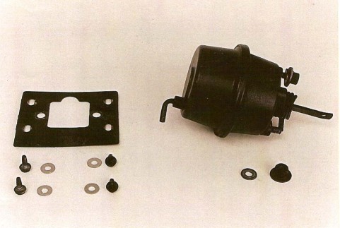
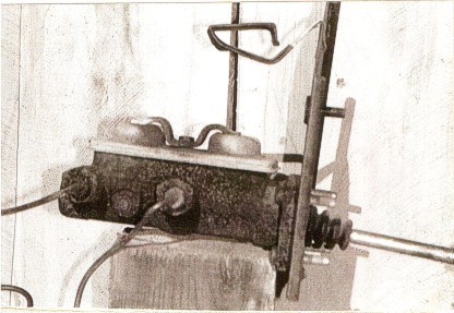
#3. This is the correct master cylinder for a Daytona with manual drum brakes. Note that there is no paint on the master cylinder or the cover. The mounting plate is painted gloss black. The left-side fluid lines are correct.
#4. This is the right forward inner fender. Everything shown here is correct. Note the lack of body color paint on the holes where the 1969 fender mounted to the inner fender forward (arrows).
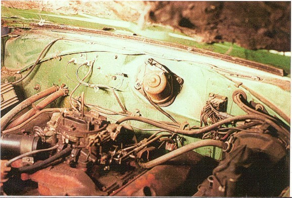
#5. This is a view of a non-original 440 Daytona firewall. Note these incorrect things: electronic control box, missing voltage regulator, red heater hoses. Also note some correct things. This car has a hood pad even though it did not have undercoating under the floor. A hood rear seal is used, however, no front seal is used on a Daytona hood.
The photos shown below are from left to right:
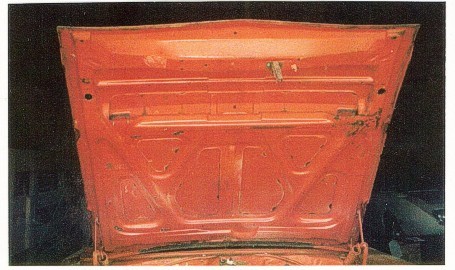
#1. Contrary to what most people tell you, a Daytona hood is NOT just a 1970 Charger hood. Shown here is a correct original Daytona hood. Note that the area in front of the latch does not have the "strength ribs". (Photo by Jim McCauley)
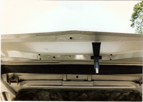
#2. Here is a close-up photo of the latch area of an authentic Daytona hood. (Photo by Wayne Perkins)
#3. Shown here is the same are of a 1970 Charger hood. Note the "strength ribs" on either side of the hood spring. (Photo by Wayne Perkins)
#4. This photo shows the inner fender and cowl area. Note that the ground cable from the engine to the cowl is almost completely painted orange (this is a 440 car). The hood hinge bolts shown here are correct. There are two large-headed bolts and one small-headed bolt.
The next group of photos is as follows from left to right:
#1. This photo shows the inner right rear side of a Daytona fender. These early-run fenders have a small tab (lower arrow) that is not seen on regular 1970 Charger fenders. Note that there is a lack of color coating or undercoating on the gray primer on all of the fender underside. Also notice the lack of a clip on the mount for the splash shield.
#2. This is a new replacement fender for a 1970 Charger. The antenna hole was crudely cut out. Note the lack of the Daytona-only tab as is pointed out in the first photo. Also notice the clip is on this fender for mounting the splash shield.
#3. This last photo shows this part of the fender mounted on the car.
The photos below from left to right:
#1. This is a view towards the rear of the inner right front fender. The holes in the fender are incorrect (arrows). The red heater hoses are also incorrect.
#2. This photo shows the inner right early 1969 Charger R/T fender. Notice the bolt attaching the heater hose bracket rather than a screw.
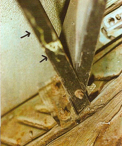
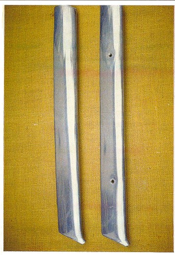
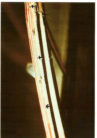
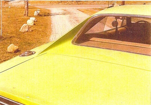
#3. Here is a comparison of the Daytona's A-pillar stainless moulding (left) to the Superbird's A-pillar moulding. The Superbird uses screws through the face of the moulding. The Daytona has hidden screws that go at an angle through the inboard edge, right beside the windshield glass.
#4. This is the A-pillar moulding installed on the Daytona.

The photos below are from left to right:
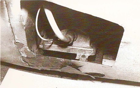
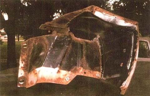
#1.In this first photo you can see the original 1969 Charger window plug still in place. The arrow shows the screw hole from the removal of the original clip. A new screw with washer attaches the headliner. Most cars still have broken glass inside this area where the assembly line workers simply smashed in the glass to get rid of it. Then the Daytona fastback rear window plug was installed.
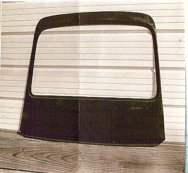
#2. This is the inside view of the Daytona rear window plug.
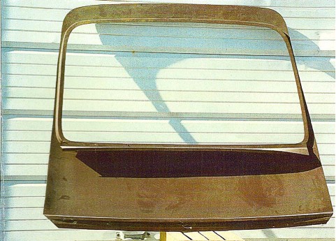
#3. The outside view of the Daytona rear window plug.
#4. The rear window area of the 1969 Charger R/T before the Daytona conversion.
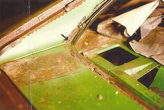
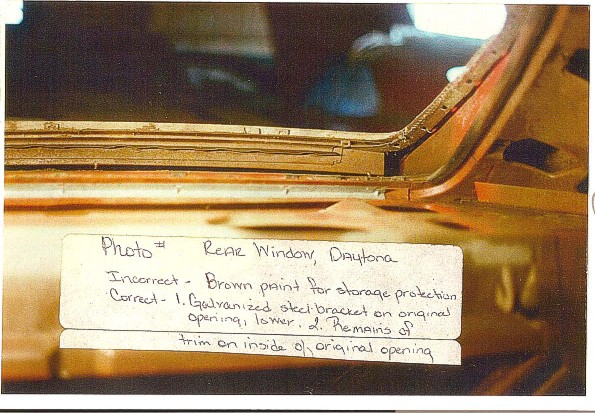
#5. Looking from the inside out, of the
Daytona rear window area, Note the brown paint was applied for storage
protection. It is not correct.
The galvanized steel bracket on the lower original opening is correct. Also note
the remains of trim on the inside of the original opening.
Shown in the photos below from left to right;
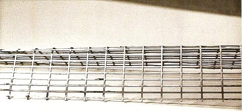
#1. This grille screen material is correct for all Daytonas.
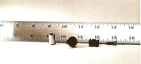
#2. This is the clip and screw for the grille frame attachment, underside. The clip is uncommon "J" shaped. No other cars we know of used it. The screw is chrome and is also used on the interior.
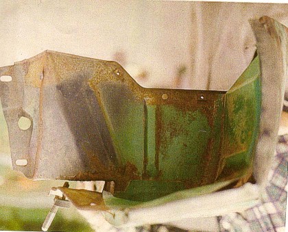
#3.This is a view of the right forward Daytona fender. There seems to be more green paint on the support than usual. Note the flat black paint. Note the lack of black on the green where the fender-to-valance seal was attached. The nose-to-fender seal length is incorrect here.
#4. This last photo shows the inner liner on the bottom of the door. It's heavy plastic and was attached with glue and tape. It was installed originally to protect the door panel from moisture.
| MAIN PAGE | TABLE OF CONTENTS |